Introduction to Arduino and LEDs
Overview
In this lesson, you will learn the fundamentals of using an Arduino board to control LEDs (Light Emitting Diodes). LEDs are essential components in electronics, and Arduino is a popular microcontroller platform that allows you to control various electronic components easily.
Prerequisites
Before starting this lesson, make sure you have the following:
- An Arduino board (any model will work).
- A computer with the Arduino IDE (Integrated Development Environment) installed.
- A USB cable to connect the Arduino board to your computer.
- A few LEDs (any color).
- Resistors (220 ohms recommended) for each LED.
Understanding LEDs
LEDs are small, low-power light sources used in various applications, including indicator lights, displays, and decorative lighting. They come in different colors and are easy to work with due to their simplicity.
LEDs have two legs: the anode (+) and the cathode (-). The longer leg is the anode, and the shorter leg is the cathode. To work correctly, LEDs must be connected in the correct orientation.
Circuit Setup
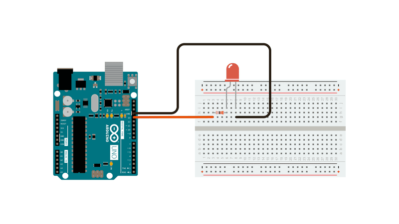
Before connecting the LEDs to the Arduino board, let's create a simple circuit. Connect the components as follows:
- Connect the longer leg (anode) of the LED to the digital pin 13 on the Arduino board.
- Connect the shorter leg (cathode) of the LED to a resistor (220 ohms) and then to the Arduino's GND (ground) pin.
Arduino Code
Next, open the Arduino IDE on your computer and write the following code:
void setup() {
pinMode(13, OUTPUT);
}
void loop() {
digitalWrite(13, HIGH);
delay(1000);
digitalWrite(13, LOW);
delay(1000);
}
Code Explanation
-
The
setup()function is called once when the Arduino board starts. In this function, we set pin 13 as an output using `pinMode(13, OUTPUT);`. -
The
loop()function is continuously executed after the `setup()` function. Inside this function, we turn on the LED by setting the digital pin 13 to `HIGH` using `digitalWrite(13, HIGH);`. We then introduce a delay of 1000 milliseconds (1 second) using `delay(1000);`. -
After one second, we turn off the LED by setting the digital pin 13 to `LOW` using `digitalWrite(13, LOW);`. We again introduce a delay of 1000 milliseconds.
The loop() function will keep repeating these steps, resulting in the LED blinking on and off every second.
Uploading the Code
-
Connect the Arduino board to your computer using the USB cable.
-
Select the appropriate board and port in the Arduino IDE from the Tools menu.
-
Click the Upload button (the right-pointing arrow) to upload the code to your Arduino board.
Testing
Once the code is uploaded, you should see the LED connected to pin 13 of the Arduino board blinking on and off at 1-second intervals.
Experimenting
Now that you have a basic understanding of controlling LEDs with Arduino, try experimenting with different pins and timings in the code to control multiple LEDs simultaneously or create custom patterns.
Remember to adjust the circuit connections accordingly when using different pins.
Conclusion
In this lesson, you learned the fundamentals of using Arduino to control LEDs. LEDs are versatile components, and with Arduino, you can create various lighting effects and automation projects. Keep exploring and experimenting with Arduino to expand your knowledge and skills in electronics and programming. Happy tinkering!